Memory Map and Boot Flow
Memory Map
The following image shows the memory map of Atom-based SoCs.
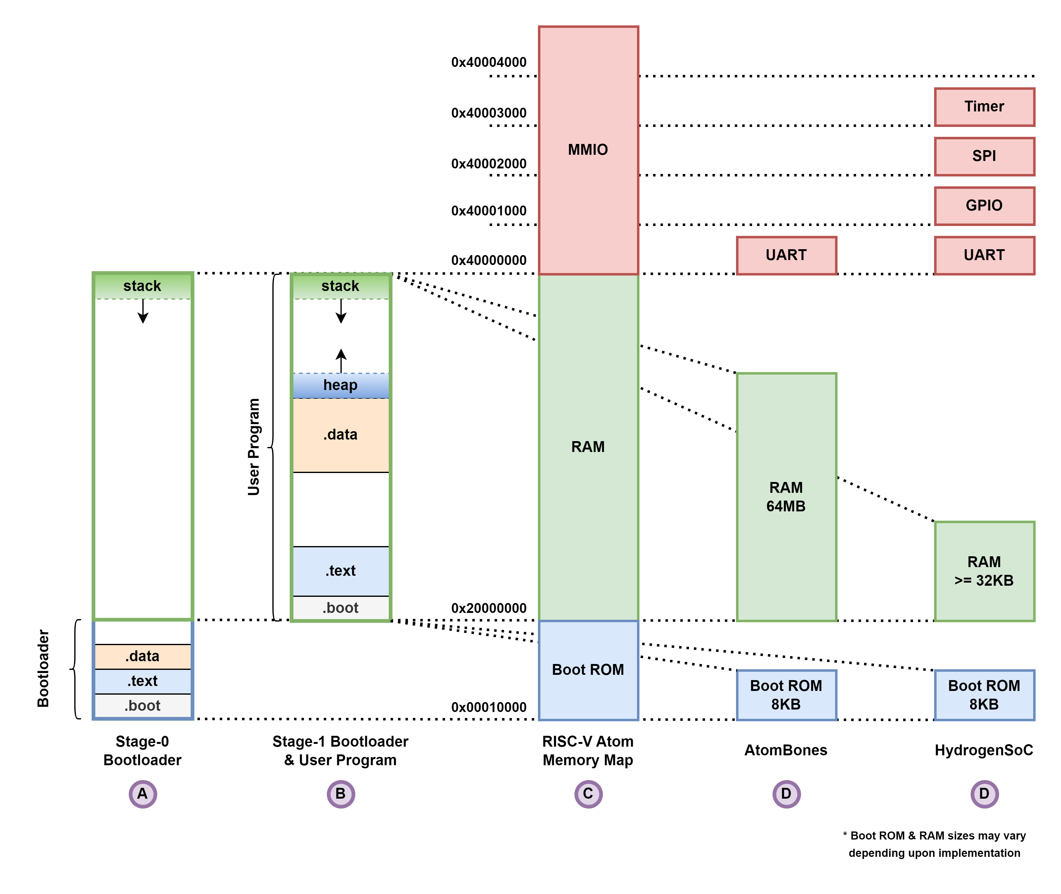
The column C shows the memory map template for all RISC-V Atom based SoCs. Column D and E show the memory map for AtomBones and HydrogenSoC respectively.
Boot Flow
Upon reset, the core jumps to the reset vector (default: 0x10000) which points to the start of BootROM. RISC-V Atom
BootROM includes a stage-0 bootloader that is automatically built and included when building the AtomSim or running FPGA
builds. The stage-0 bootloader uses RAM for stack. It initializes the platform, loads the user program in RAM and finally
transfers control to the user program. The user program often includes a stage-1 bootloader which sets up the runtime
environment and standard library before executing the application.
To know more about the stage-0 bootloader, see this page.